| |
Digital Pump Controller For Dewatering / Sewerage Systems |
| |
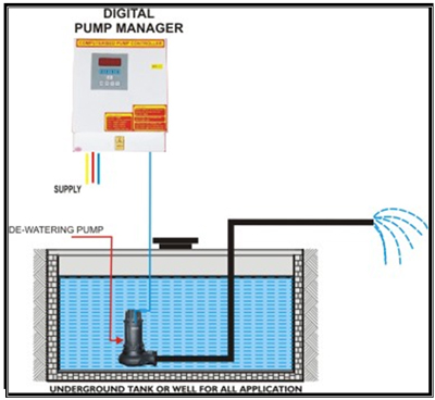
Digital pump manager is designed with advanced technology of microprocessor-based system. It is the safest and complete failure proof solution for long life and trouble free operation of the pumps ensuring continuous and automated pumping operation. Our design criterion has been built-in absolute reliability for entire life of the equipment. |
| |
DO YOU KNOW WHY PUMP MOTOR BURNS ? |
| |
| Over current |
Over load, voltage fluctuations, mechanical and electrical malfunctioning, phase failure (Single phasing) |
| Under current |
Dry run, reverse rotation, mechanical failure, phase failure (Single phasing) |
|
| |
WHAT CAN WE DO ? |
| |
Remember : Motor does not fail because of voltage but it burns because of current.
To Safe guard pump motor : We can monitor and control the current variation for its higher and lower allowable value.
Padmansha’s digital Pump manager positively monitors and controls current variations and safe guard’s pump set at any time of critical operation.
Digital pump manager also controls the water level in overhead tank, thus avoiding overflow and dry running of the Pump. |
| |
FEATURES |
| |
 |
Operates on two levels of the Sump tank. |

|
No separate starter required. |
 |
Minimum number of parts and hence less chances of failure |
 |
All the parts are plug-in type and hence very easy to maintain |
 |
Digital display of motor current, set parameters and faults |
| |
All the system parameters are code-locked. |
| |
Auto / manual mode of operation. |
| |
Protections are not bypassed even in manual mode |
| |
Following protections are inbuilt to the system |
| |
b. Under Current
c. Dry run
d. Low voltage
e. High voltage
f. Single phasing preventer. |
| |
|
|
| |
Compared parameter |
Digital Pump Manager |
Conventional Control Panel |
Over Load |
Micro controller Based over load |
- Trips instantly even at current that is set.
- Very long life since no heating element.
|
Extra Thermal Over Load Relay |
- Extra overload has to be added
- Trip Time depends on current. As current Increases, time reduces.
- .Wear & tear due to Continuous heating.
|
Under Current |
Inbuilt Under current Sensor |
Inbuilt under current sensor. |
Extra Electronic Unit |
An Extra Electronics Circuitry needs to be added in the Panel. |
Ampere meter |
Digital |
Inbuilt Digital Ampere Meter & can show difference of even 100 MA. |
Extra Moving coil meter |
Extra Ampere Meter has to be added |
Single
Phasing
Preventor |
Voltage as well as Current Based
SPP |
Motor current gets affected when motor is not getting right voltage so any problem in supply line is sensed & motor is saved. |
Voltage Based SPP |
Line voltage reaching the panel but not reaching the motor, this can not be sensed by voltage based SPP and so motor may burn. |
Dry Run Protection |
Inbuilt Dry Run Sensor |
Pump running dry is sensed without external flow or liquid sensor |
Extra Electronic Unit |
Conventionally not included & they depend on the mechanical water or flow sensors. |
Fault Finding |
Digital Display of Faults |
Direct reading of Fault on display. Hence easy and reliable fault location and removal |
No or primitive fault indication |
Fault finding is difficult and tedious. |
Maintenance |
Less components, Less wiring, latest technology |
Less number of components and less wiring means fewer maintenance issues, latest plug-in design makes it easy to change cards / parts and hence very less down time. |
Lots of wiring and complex wiring inside |
More components and wiring means frequent maintenance requirements. Not easy to replace any part. |
Reliability |
Latest Micro-controller Technology |
Highly reliable due to use of low voltage micro-controller control card and the use of best quality material |
Analog Components |
Limited reliability because reduced accuracy of analog components. |
|
| |
OPERATION |
| |
 |
| |
 |
| |
The unit operates in two modes, Auto and Manual. The two modes and operation according to the selected mode is as follows…. |
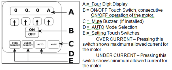
- AUTO MODE – In this mode, the motor is operated completely automatically according to the water level in sum tank. The operation is as follows…
- If in manual mode, the unit starts operating in AUTO MODE, whenever the AUTO button is pressed.
- The display in auto mode is steady and does not blink.
- Whenever the there is missing phase condition, the display will keep showing “ S. P. P. “, it will stop the pump and wont operate at all.
- The motor is started automatically when the water reaches the upper level of the sump tank.
- The motor is stopped automatically whenever water goes below the lower level of the sump tank. The display will start showing “ L. t E “ for Lower Tank Empty.
- The motor is stopped automatically whenever the motor current goes above the set over current limit, then
- The digital display start showing “ O. C ” for over current
- The display starts blinking
- If level is above the upper level of the sump tank, the unit will try to start the pump again after 15 minutes.
- If the error occurs again and again for 10 times, the unit will be shut off permanently and will not start until manually started by user or “AUTO” button is pressed. In both cases, the count is reset and in auto mode the unit will start the pump 10 times.
- The motor is stopped automatically whenever the motor current goes below the set under current limit, then
- The digital display start showing “ U. C ” for over current
- Same as ii above
- Same as iii above
- Same as iv above
- The motor is stopped if the winding temperature sensed goes above set value. The unit will start showing “ t E. H I “ and wont start the pump till the temperature goes down again.
- The motor is stopped whenever the moisture sensor inside the motor gets shorted. The unit starts showing “ g L. L E ” for Gland Leakage.
- MANUAL MODE – Manual mode is identical to auto mode with the difference is the motor is not started automatically. The difference between AUTO mode and MANUAL mode of operation is as below…
- If in auto mode, the unit goes in manual mode whenever the motor is started or stopped using the ON/OFF button.
- The display in manual mode keeps blinking.
- The pump will not start automatically even if water / sludge is above the upper level in sump tank or in any other condition.
- The motor will stop for all the reason explained in AUTO mode.
|
| |
INSTALLATION |
| |
 |
| |
DISPLAY AND FAULT FINDING |
| |
 |
When the motor is running, The unit shows actual motor current. This is realized by the “ A “ as the fourth digit.
Everything is normal. |
 |
When the motor is off and it was not turned off due to sump tank empty or any other fault, it keeps displaying as shown.
Everything is normal. |
 |
Lower Tank Empty. Whenever the unit is in AUTO mode and is stopped due to Sump Tank Empty. The display is as shown.
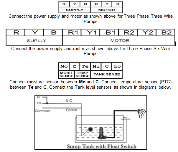
In case the tank is not empty, check the lower level sensor connected between “ C “ and “ Lo “ of the sensor terminals. |
 |
Single Phasing Preventer. Whenever there is a missing phase or high amount of voltage imbalance occurs this fault is seen. This could also arise due to reverse voltage coming at the supply terminals.
- Check incoming supply for missing phase condition. If one of the phase is missing or very low, remedy the condition.
- If all three voltages are correct, change any two wires of the incoming supply and try again. If the fault is removed, take care of the motor connections.
|
| |
|
 |
Under Current. Whenever the motor is taking current below the set under current value, the motor is turned OFF and the shown message is displayed. Cause and remedy are as described below…
- Dry Run – Under Current can happen when the motor is running on no load condition. That is the sump tank is empty. Verify the float switch / lower level probe connected in the sump tank.
- Motor is not connected properly – make sure the motor wires are connected properly and do the needful.
- If still the problem is not resolved contact customer care.
|
| |
|
 |
Over Current. Whenever the motor is taking current above the set Over current value, the motor is turned OFF and the shown message is displayed. Cause and remedy are as described below…
- Blockage – make sure the motor is able to throw water / sludge out and there is no blocked.
- Low voltage – make sure correct voltage reaches the supply terminals of the unit
- If this fault keeps repeating, contact customer care.
|
| |
|
 |
Short Circuit. If the current taken by the motor goes beyond acceptable values, it shows this message.
If this fault occurs, do not attempt to start the pump again and again.Contact customer care.
|
| |
|
 |
Temperature High. If the temperature of the winding increases and the PTC opens, this message is displayed.
- Make sure the temperature sensor wire is connected properly.
- If persists, contact customer care.
|
| |
|
 |
Gland Leakage. Moisture Sensor terminals are shorted.
- Make sure there is no short between Moisture Sensor terminal points.
- Contact customer care.
|
|
| |
 |
| |
 |
|
|


