| |
Electronic Motor Starter |
| |
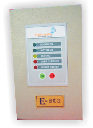 |
Electronic Starter with Complete Motor Protection |
| |
| Do you Know why pump motor burns? |
| |
OVER CURRENT
Over Load, Voltage Fluctuations, Mechanical & Electrical
Malfunction, Phase Failure
UNDER CURRENT
Dry Run, Reverse Rotation, Mechanical Failure & Phase Failure
(Single Phasing) |
| |
| What Can we Do? |
| |
Now we know that the motor does not fail because of voltage but it burns because of Current.
So by monitoring and controlling the current variations, keeping them in its higher and lower allowable values, we can safeguard our motor!!! |
| |
|
| Highlights |
| |
 Rugged Design. Reliable and Tested Technology Rugged Design. Reliable and Tested Technology
 Very Easy to Install and Maintain Very Easy to Install and Maintain
 Complete Protection of Pump Motor Complete Protection of Pump Motor
 Only Three parts and hence very low Maintenance Only Three parts and hence very low Maintenance
 Plug and Play Design for Very Easy Maintenance Plug and Play Design for Very Easy Maintenance
 Designed for Million Operations Designed for Million Operations
 No Exposed Contacts and Hence no Wear and Tear No Exposed Contacts and Hence no Wear and Tear |
| |
| Electronic Starter with Complete Motor Protection |
| |
 |
BENEFITS
Saves Electricity and water
Saving in operating cost
Increase in Motor Life
Increase in Safety |
|
| |
  |
Applications
High rise building
Pump
Sewerage Pumps
Dewatering
Agriculture/Borewell
Hotels
Societies |
|
| |
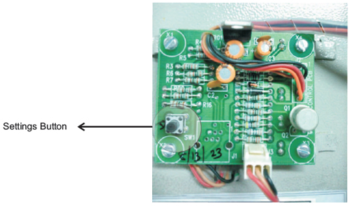
| FUNCTIONAL LAYOUT |
| |
 |
| |
 |
| |
| MODES OF OPERATION |
| |
1) Unprotected
This mode is when the auto setting for the motor protection is not done. This is not recommended mode of operation, only to be used by trained professionals for setting up a new system.
1) The Setting LED is blinking
2) The motor can be started and stopped with the ON / OFF button
3) Motor protection features are not set, the motor can burn with Under Current or
Over Current and the unit would not trip.
2) Protected
This mode is the normal operational mode for the unit. Auto Setting procedure
carried out and the motor protection settings are in effect. in this mode,
1) The Setting LED is glowing
2) The motor can be started and stopped by the ON / OFF buttons
3) Motor protection features are set. Whenever the motor draws more than the set over current limit or when it draws less than under current limit, the motor is stopped and the related LED is lit. |
| |
| SETTING PROCEDURE |
| |
1> Turn ON the supply.
- “SETTING” LED flashing.- Setting Not Done.
- “SETTING” LED OFF - Old Setting in effect. -
- Press settings button to remove old setting. LED should now start flashing.
2> Turn ON the motor and make sure it is not revolving in opposite
direction
.
3> When motor is running OK for 1 minute, press the “setting” button. Setting LED should keep glowing.
Installation Complete.
Your Pump is now completely protected |
| |
| Electronic Starter with Complete Motor Protection |
| |
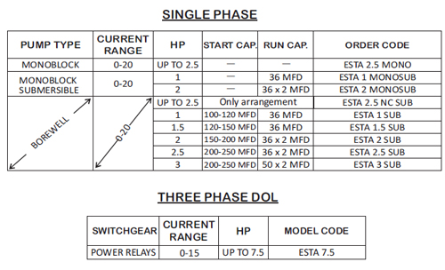
| Model Selection Chart |
| |
| SINGLE PHASE |
| |
 |
| |
| Electronic Starter with Complete Motor Protection |
| |
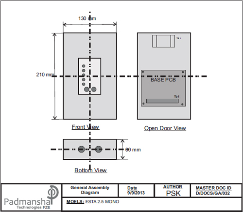
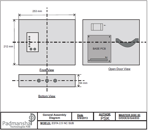
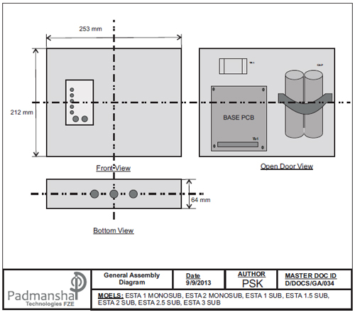
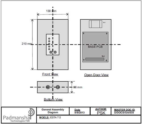
| General Assembly |
| |
 |
| |
 |
| |
 |
| |
 |
| |
| Electronic Starter with Complete Motor Protection |
| |
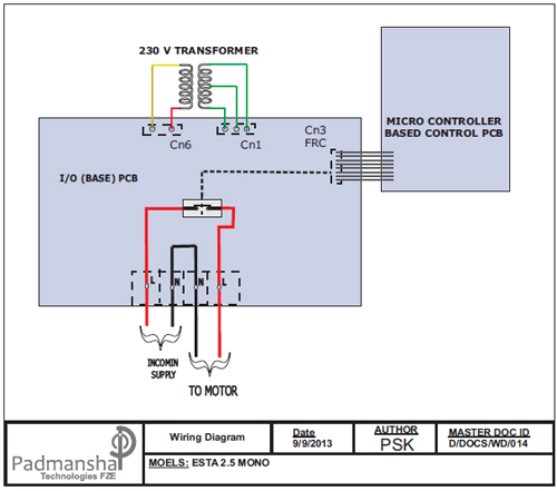
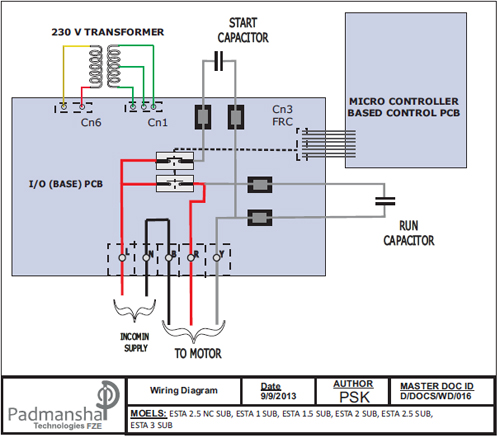
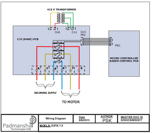
| Wiring Diagrams |
| |
 |
| |
 |
| |
 |
| |
| Terminal Diagrams |
| |
1) Single Phase Mono-block Pump Controller, without capacitor
- Models: ESTA 2.5 MONO |
| |
 |
| |
2 ) Single Phase Submersible Pump Controller, with capacitor
- Models: ESTA 1 MONOSUB, ESTA 2 MONOSUB, ESTA 2.5 NC SUB,
ESTA 1 SUB, ESTA 1.5 SUB, ESTA 2 SUB, ESTA 2.5 SUB,
ESTA 3 SUB |
| |
 |
| |
3 ) Three Phase Pump Controller
- Models: ESTA 7.5 SUB |
| |
 |
| |
 |
| |
 |


